<Intersection direction="row-to-col">
    <IntersectionPath>
        <Path from="relationship_PartSpecification"/>
    </IntersectionPath>
    ...
</Intersection>Grid Browser - Administration Guide : Intersection
21 March 2016
1. Intersection
The intersections are shown in the right area of the grid and represent the connections between the row and column object. The intersections are calculated by selecting data on the row-object or the column-object, in order to find the other object. How to get from one object to another is defined within the intersection path.
An example configuration is shown below:
The definition above would correspond to a data model like below.
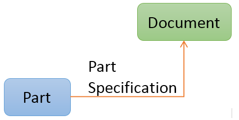
Figure 1. Intersection path illustration
1.1. Intersection Paths
An intersection path defines how to traverse from an object on the row or column axis to the object on the other axis. The path can be as simple as just one relationship between these, but can also be more complicated like having several levels or using relationship that starts from a relationship or ends on a relationship.
Below are some examples how to construct the intersection path depending on the data model.
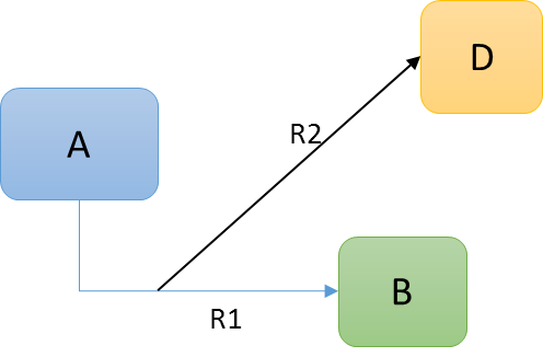
Example 1:
Assuming that object A is shown on the row axis and object C is shown on the column axis
<Intersection direction="row-to-col">
    <IntersectionPath>
        <Path from="R1"/>
        <Path to="R2"/>
    </IntersectionPath>
    ...
</Intersection>
Example 2:
Assuming that object A is shown on the row axis and object C is shown on the column axis
<Intersection direction="row-to-col">
    <IntersectionPath>
        <Path from="R1"/>
        <Path fromRel="R2"/>
    </IntersectionPath>
    ...
</Intersection>
This example illustrates how we to traverse from a relationship into another relationship that is connected from a relationship to a businessobject.
Example 3:
Assuming that object A is shown on the row axis and object C is shown on the column axis
<Intersection direction="row-to-col">
    <IntersectionPath>
        <Path **from**="R1" targetIsRel="true" targetQualifier="to"/>
    </IntersectionPath>
    ...
</Intersection>
This example illustrates how we to traverse from a relationship that points to a relationship that is connected between two business objects.
Example 4:
Assuming that object A is shown on the row axis and object C is shown on the column axis
<Intersection direction="row-to-col">
    <IntersectionPath>
        <Path from="R1" targetIsRel="true" targetQualifier="from"/>
    </IntersectionPath>
    ...
</Intersection>
This example illustrates how we to traverse from a relationship that points to a relationship that is connected between two business objects.
Example 5:
Assuming that object A and B including R1 (or only B+R1) is shown on the row axis and object D is shown on the column axis and R2 is a connection from R1 pointing to object D.
<Intersection direction="row-to-col">
    <IntersectionPath>
        <Path fromRel="R2"/>
    </IntersectionPath>
    ...
</Intersection>
This example illustrates how we to traverse from relationship R1 via relationship R2 to object D.
Example 6:
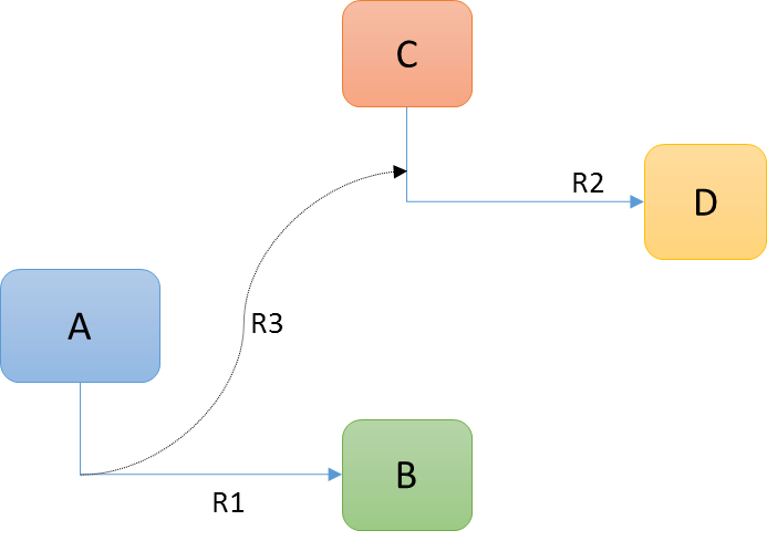
Assuming that object A and B including R1 (or only B+R1) is shown on the row axis and object D and R2 is shown on the column axis and R3 is a connection from R1 pointing to relationship R2.
<Intersection direction="row-to-col">
    <IntersectionPath>
        <Path fromRel="R3" targetIsRel="true" targetQualifier=""/>
    </IntersectionPath>
    ...
</Intersection>
This example illustrates how we to traverse from relationship R1 via relationship R3 to relationship R2.
Note the special use of the attribute "targetQualifier" here. In case we end on a relationship, this should be empty.
1.2. Cell States
Each intersection can satisfy one or more states. Each state is typically shown with a different color, and each state typically has its own set of element actions available.
You can have as many cell states as you wish, however, an intersection that satisfies more than one state will only use the last defined cell state (according to the order they are defined within the configuration).
A simple cell state definition example below:
<Intersection direction="col-to-row">
    ...
    <CellStates>
        <CellState id="s0" color="red" ifConnected="false">
            <Label>Not Connected</Label>
        </CellState>
        <CellState id="s1" color="green" ifConnected="true">
            <Label>Connected</Label>
        </CellState>
    </CellStates>
</Intersection>
1.2.1. Legend
The legend will show the possible states, and their respective color. It is however possible to exclude a particular state from the legend by setting the attribute "showInLegend" to false on the CellState element.
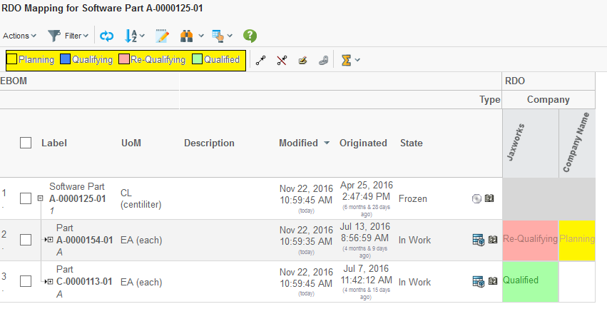
Figure 2. Legend
1.2.2. Conditions
When a cell state applies to an intersection that is being connected, e.g. there exists a connection instance between the row and column object, it is possible to construct more complex cell states that depends upon some value on the connection or from an object on either the to- or from- side of the connection.
This is accomplished by adding Conditions to a CellState element.
A CellState can have multiple Conditions, in this case- all Conditions must be satisfied in order for an element to satisfy the cell state.
The example below shows a basic example using conditions.
<CellState id="s2" ifConnected="true" color="#FFFF00">
<Condition>
<Expression>
$<attribute[attribute_SourceQualificationStatus]>
</Expression>
<Operator>==</Operator>
<Value>Qualifying</Value>
</Condition>
<Label>Qualifying</Label>
</CellState>The example below illustrates how to use more complex conditions by
using the evaluate[] feature in ENOVIA.
<CellState id="s5" ifConnected="true" color="magenta" fontColor="black">
<Condition>
<Expression>
evaluate[MX_CURRENT_TIME - attribute[Date Shipped]]
</Expression>
<Operator><</Operator>
<Value>0</Value>
<Format>real</Format>
</Condition>
<Label>Shipped</Label>
</CellState>| The data-type for the returned value above will be "date". In order to make the comparison, one needs to convert the returned value to a numeric value. This is done via the "Format" element. |
The example above can also be written as:
<CellState id="s5" ifConnected="true" color="magenta" fontColor="black">
<Condition>
<Expression>attribute[Date Shipped]</Expression>
<Operator><</Operator>
<Value>${CURRENT_DATE}</Value>
</Condition>
<Label>Shipped</Label>
</CellState>In this case, the macro ${CURRENT_DATE} has been used to substitute the
value with the current date.
Another example using multiple conditions is shown below:
<CellState id="s6" ifConnected="true" color="yellow" fontColor="red">
<Condition>
<Expression>attribute[Agreed Unit Price]</Expression>
<Operator>></Operator>
<Value>10000</Value>
</Condition>
<Condition>
<Expression>attribute[Agreed Unit Price]</Expression>
<Operator><</Operator>
<Value>20000</Value>
</Condition>
<Label>Expensive</Label>
</CellState>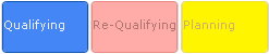
1.3. Performance Consideration
The configuration defines the direction of the relationship. E.g. whether to start looking from the row object or the column object. At the bottom line, this will result in at least two select statements that are applied to either the row objects or the column objects.
Consider following example:
On the column axis, objects of type Organization are loaded. On the row axis, objects of type Part are loaded. A Part can be associated to an Organization via the relationship "Supplied By". This relationship is routed from the Part to the Organization (see picture below).
Depending on how the Grid Browser is configured, one will start on the "Organization object" and traverse in the "to" direction and find the "Part object" OR start on the "Part object" and traverse in the "from" direction and find the "Organization object".
This would be configured within the Grid Browser configuration as:
<Intersection direction="col-to-row">
    <IntersectionPath>
        <Path to="relationship_SuppliedBy"/>
    </IntersectionPath>
    ...
</Intersection>
Or:
<Intersection direction="row-to-col">
    <IntersectionPath>
        <Path from="relationship_SuppliedBy"/>
    </IntersectionPath>
    ...
</Intersection>
E.g. the first approach results in the following statements to be selected on the Organization objects:
-
to[Supplied By].id
-
to[Supplied By].from.id
The second approach results in the following statements to be selected on the Part objects.
-
from[Supplied By].id
-
from[Supplied By].to.id
The end result will be the same. The problem will become visible if/when an Organization object has a larger amount of Part objects connected; e.g. the number of connections pointing to the Organization object are large.
With the first approach, the select statements will return a larger data-set, which results in degraded performance.
The conclusion is that one should avoid traversing in a direction where the amount of possible connections is high. If you aren’t able to predict this or the number of connections is same or similar independent of the direction, you should strive to make your IntersectionPath going in the "from" direction.
1.4. In Cell Editing
As of 2011.3.0, it is possible to allow the user (in edit mode) to modify intersection information directly in the table (in cell edit).
The fields being open for edit is configured in the Grid Browser configuration and an example of how it could look like in the user interface is shown below:
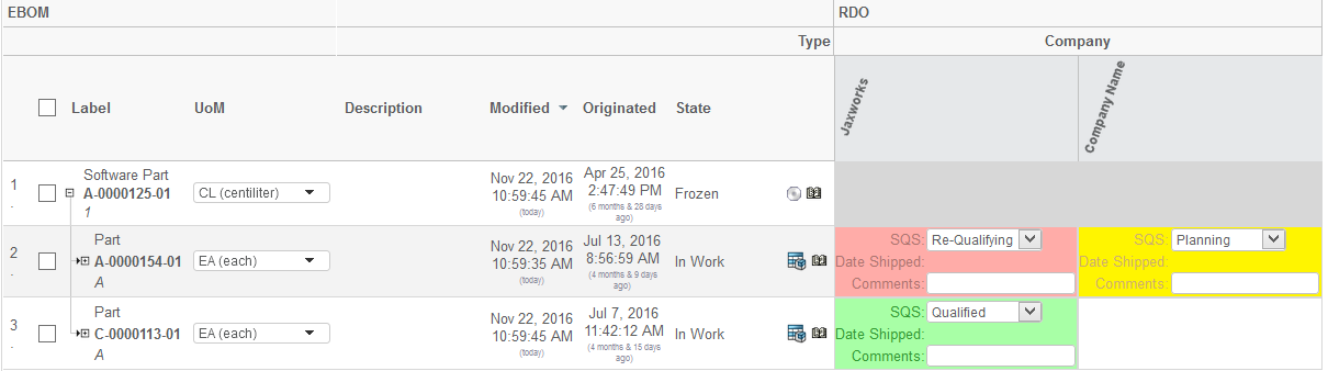
Figure 3. In-cell edit
The configuration to enable editable fields in the intersection area is shown below:
<Intersection direction="col-to-row">
    ...
    <EditableFields>
        <Field>
            <Label>SQS:</Label>
            <Attribute>attribute_SourceQualificationStatus</Attribute>
            <Setting name="Update UI" value="true"/>
        </Field>
        <Field>
            <Label>Date Shipped:</Label>
            <NoWrap>true</NoWrap>
            <Attribute>attribute_DateShipped</Attribute>
            <Setting name="Editable States" value="s1,s2"/>
        </Field>
        <Field>
            <NoWrap>true</NoWrap>
            <Attribute>attribute_Comments</Attribute>
        </Field>
    </EditableFields>
The configuration details are described in this chapter.
If you are enabling edit to a field that changes the state of an intersection (see this chapter), then you can apply the setting “Update UI" with the value set to true. That will cause the field to be completely updated upon edit. The reason for not doing this by default is due to performance reasons.
Also, if you want to disable edit of fields in particular states, then you can use the setting “Editable States". The value should be a comma separated list of state-id’s, which the field is editable in.
1.5. Custom JPO as Element- or Global- Action
See the following code example for how such a JPO could be written:
import matrix.db.Context;
import matrix.db.JPO;
import com.technia.tvc.gridbrowser.util.JPOParam;
import com.technia.tvc.gridbrowser.util.ElementParam;
import com.technia.tvc.gridbrowser.util.Parameters;

public class ${CLASSNAME} {
    public ${CLASSNAME}() throws Exception {
    }

    public ${CLASSNAME}(Context ctx, String[] args) throws Exception {
    }

    public void perform(Context ctx, String[] args) throws Exception {
        JPOParam param = (JPOParam) JPO.unpackArgs(args);
        ElementParam elements = param.getElementParam();
        Parameters parameters = param.getParameters();

        for (ElementParam.Element e : elements) {
            String rowObjectId = e.getRowObjectId();
            String colObjectId = e.getColObjectId();
            String connectionId = null;
            if (e.hasConnectionId()) {
                connectionId = e.getConnectionId();
            }
            // PERFORM ACTION
        }
    }
}
In order to being able to compile such a JPO, you must ensure that
the MX_CLASSPATH contains the TVC grid browser JAR file.
|
1.5.1. Public API
The API for those classes used by a JPO, is shown below. The methods are self-describing.
The JPOParam class has the following methods:
ElementParam getElementParam()
Parameters getParameters()
The ElementParam class has the following methods
int getCount()
ElementParam.Element get(int index)
ElementParam.Element[] getElements()
The ElementParam.Element class has the following methods
String getRowObjectId()
String getRowRelId()
String getColObjectId()
boolean hasConnectionId()
String getConnectionId()
The Parameters class, has the following methods:
String[] getParamValues(String paramName)
String getParamValue(String paramName)
String getParamValue(String paramName, String defaultValue)
1.6. Disabling a Column or Row
It is possible to disable a complete row or column based upon some condition that is checked against the object on the row-axis. This could for example look like this:
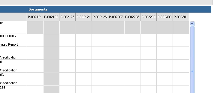
Figure 4. Disabled rows / columns.
To configure this, look at the following configuration example.
<GridBrowser>
    <Rows>
        <DisableIf>current == "Create" OR current == "Preliminary"</DisableIf>
    </Rows>
    <Columns>
        <DisableIf>name == P*22</DisableIf>
    </Columns>
</GridBrowser>
These statements are evaluated per object on the axis they are defined for. Such a statement should typically return TRUE or FALSE in order to work properly. To test if an expression is valid and correct is easiest done from MQL, like this example:
<MQL> pri bus 1.2.3.4 select evaluate[current == "Create" OR current == "Preliminary"] dump;
This must return either TRUE or FALSE in order to be useful.
The select evaluate[] clause in MQL were introduced in 10.6.3
|
1.6.1. Dynamic Values
Sometimes, there is a need to be able to evaluate an expression were something depends upon the starting object (e.g. the object that the Gridbrowser were launched for/with).
It is possible to use macros within the <DisableIf> elements. A
macro is something that is replaced with a value at runtime.
<Columns>
    <DisableIf>to.from.id ~~ "${OBJECTID}"</DisableIf>
</Columns>
This macro contains the ${OBJECTID} macro, which refers to the object-id of the starting object. The macro is resolved before it is being evaluated.
Examples of other macros that would work:
-
${USER}
-
${TYPE}
-
${NAME}
-
${REVISION}
-
${CURRENT}
-
${POLICY}
-
${OBJECTID}
-
${OID}
-
${attribute[Weight]}
The expression applies by default on the object. It is possible to make it apply to the relationship associated with the column or row object. In that case, you can define the expression like:
<Columns>
    <DisableIf relationship="true">...</DisableIf>
</Columns>